Photo by Taylor Vick on Unsplash
What is Spanning Tree Protocol? How does it work in Cisco Catalyst switches?
In this article, I will be covering Spanning Tree Protocol (STP), and how it operates in Cisco Catalyst switches.
Just a fair warning: this is going to be a long article.
I will be covering this topic in two parts. This article will cover the theory of spanning-tree protocol. In the next article, I will demonstrate how to configure RPVST+.
Let's get started.
Disclaimer: I am going to begin publishing articles on different network protocols with practical demonstrations of implementing these protocols in a network. The goal is to help others learn how these protocols work, to further prepare them for their CCNA or CCNP certification.
Introduction
Spanning Tree Protocol (STP) is a protocol developed in the mid-1980s and implemented in the early 1990s. The goal of the spanning tree protocol is to prevent loops on Ethernet and fiber networks. See this Wikipedia article for more info on how the spanning tree protocol came about.
Disclaimer
This article focuses on Cisco's latest implementation of STP, which is RPVST+. This does not focus on the open standard STP which is implemented on non-Cisco switches.
Spanning Tree Protocol (STP)
Overview
Spanning Tree Protocol (IEEE 802.1D) is a protocol that prevents broadcast storms over a redundant layer 2 switching domain. STP is typically enabled by default on modern managed switches.
Why spanning tree protocol matters
In an enterprise network, engineers typically design the layer 2 domain to have redundant paths to the core, where multiple links are distributed between the access layer to core layer switches. Redundancy is an important part of ensuring high availability of network resources. Having a redundant path to the network core prevents an outage if an uplink Ethernet or fiber cable fails. STP serves an important role in preventing a devastating disaster from forming: a broadcast storm.
Broadcast Storms
A broadcast storm occurs in redundant networks when an endless broadcast loop propagates across the switching domain.
Here's usually how a broadcast storm starts: first, an endpoint sends an ARP packet or some form of broadcast message to its connected switch. Next, the switch receives the ethernet frame and identifies the destination MAC address in the frame to be a broadcast MAC address. Furthermore, the switch floods the frame out of all ports. Any switches that are connected upstream from the original switch will receive the frame, identify the destination MAC address as broadcast, and then forward the frame out of all egress ports. If there is a loop in the connection, then any switches that previously received/forwarded the frame will receive it again and forward it again, creating a broadcast storm.
STP mitigates broadcast storms in the network by blocking redundant links to prevent switching loops.
I created a packet tracer activity to practically demonstrate broadcast storms. Feel free to download it and test it out.
Operation of Spanning Tree Protocol
The operation of the spanning tree protocol is broken down into several categories:
Bridge Protocol Data Unit (BPDU): the messages each switch transmits and receives as part of tracking the STP topology.
Bridge IDs & priorities
Path Cost
Port Roles
Port States
The terms "bridge" and "switch" are used interchangeably. They both mean the same thing.
Bridge Protocol Data Unit (BPDU)
The first item I'd like to cover is the bridge protocol data unit (BPDU).
In the spanning tree protocol, each switch exchanges what are known as BPDUs, which contain the following information:
Hello Time: the interval between BPDUs transmitted.
Max Age Time: the maximum amount of time to receive a BPDU before the forward delay timer begins incrementing.
Forward Delay: how long after the max age timer expires to begin transitioning to an unblocked state.
Bridge ID: identifies the switch relative to the root bridge.
Extended System ID: helps to uniquely identify the VLAN a switch is operating spanning-tree protocol. Added onto the bridge ID.
BPDUs are used between all switches in the spanning tree domain to identify and block redundant connections so a loop can be prevented.
Below we will cover the information contained in a BPDU in detail.
Hello Time
The hello time = how often to transmit BPDUs every x number of seconds. The default hello time on Cisco catalyst switches is 2 seconds. So by default, a Cisco catalyst switch will send BPDUs every 2 seconds.
Max Age Time
The max. age time = how long after a BPDU is not received a switch begins to count the forward delay timer to transition a port from blocking to forwarding. The default max. age time on Cisco catalyst switches is 15 seconds.
Forwarding Delay Time
The forwarding delay time = how long after the max. age time expires a switch port starts transitioning from blocking to forwarding. Again, this is only after the max. age time expires and no new BPDUs were received. The forward delay time will be covered in detail in further sections, so keep reading.
The hello time, max. age time and forwarding delay time can be adjusted on Cisco catalyst switches. The below commands demonstrate how to adjust the timers:
Core_Switch(config)#spanning-tree vlan 1 hello-time 4
Core_Switch(config)#spanning-tree vlan 1 max-age 20
Core_Switch(config)#spanning-tree vlan 1 forward-time 30
Bridge ID
The bridge ID field in a BPDU identifies the bridge priority. The bridge priority identifies a switch relative to a root bridge. The lower the value, the higher the precedence that it becomes a root bridge.
Root bridges SHOULD be the centralized bridge of the spanning tree topology. In a campus network, the core switch should always be a root bridge.
Traffic flows toward a root bridge in the spanning tree domain to efficiently get to its destination.
The range for bridge ID/bridge priority is 0 to 61440 in increments of 4096. Again, the lower the number, the higher the precedence. When tuning your STP topology, you will need to configure your root bridge for the lowest bridge priority.
The default bridge ID for Cisco catalyst switches is 32768.
Extended System ID
The extended system ID identifies what VLAN the spanning tree instance belongs to. For example, if you're operating a Cisco catalyst switch carrying multiple VLANs, and you're using RPVST+ as your spanning-tree mode, then each VLAN is given its own unique extended system ID to help identify each per-VLAN spanning-tree instance.
The below example shows a Cisco catalyst's show vlan brief output to show it has multiple VLANs, and show spanning-tree output to demonstrate the different extended system IDs:
*Nov  5 19:58:32.013: %SYS-5-CONFIG_I: Configured from console by consoleree
Switch1#show vlan brief

VLAN Name                             Status    Ports
---- -------------------------------- --------- -------------------------------
1    default                          active    Gi1/1, Gi1/2, Gi1/3, Po1, Po2
2    VLAN0002                         active    Gi1/0
1002 fddi-default                     act/unsup
1003 token-ring-default               act/unsup
1004 fddinet-default                  act/unsup
1005 trnet-default                    act/unsup
Switch1#show spanning-tree

VLAN0001
  Spanning tree enabled protocol rstp
  Root ID    Priority    4097
             Address     5000.0001.0000
             Cost        3
             Port        65 (Port-channel1)
             Hello Time   2 sec  Max Age 15 sec  Forward Delay 30 sec

  Bridge ID  Priority    8193   (priority 8192 --> sys-id-ext 1 <-- notates VLAN 1)
             Address     5000.0002.0000
             Hello Time   2 sec  Max Age 20 sec  Forward Delay 15 sec
             Aging Time  300 sec

Interface           Role Sts Cost      Prio.Nbr Type
------------------- ---- --- --------- -------- --------------------------------
Gi1/1               Desg FWD 4         128.6    P2p
Gi1/2               Desg FWD 4         128.7    P2p
Gi1/3               Desg FWD 4         128.8    P2p
Po1                 Root FWD 3         128.65   P2p
Po2                 Desg FWD 3         128.66   P2p Peer(STP)


VLAN0002
  Spanning tree enabled protocol rstp
  Root ID    Priority    32770
             Address     5000.0002.0000
             This bridge is the root
             Hello Time   2 sec  Max Age 20 sec  Forward Delay 15 sec

  Bridge ID  Priority    32770  (priority 32768 --> sys-id-ext 2 <-- notates vlan 2)
             Address     5000.0002.0000
             Hello Time   2 sec  Max Age 20 sec  Forward Delay 15 sec
             Aging Time  300 sec

Interface           Role Sts Cost      Prio.Nbr Type
------------------- ---- --- --------- -------- --------------------------------
Gi1/0               Desg FWD 4         128.5    P2p


Switch1#
As you see above, the spanning tree instance for VLAN 1 has an extended system ID of 1, while the extended system ID for VLAN 2 is 2.
Versions of Spanning-Tree Protocol
Before I move further on the operation of the spanning-tree protocol, you should be aware that there are both vendor-specific & open standard implementations of the spanning-tree protocol.
The open standard spanning-tree protocol is known as 802.1D for the original version and 802.1W for the more modern RSTP (Rapid Spanning Tree Protocol).
Cisco has its implementation of a spanning tree known as PVST (Per-VLAN spanning tree). PVST enables multiple unique instances of spanning trees to run across different VLANs. Cisco's version of RSTP is RPVST+ (Rapid-PVST+).
The open-standard version of PVST is MSTP (Multiple Spanning-Tree Protocol) which enables spanning-tree to run across different VLANs much like Cisco switches.
In this article, I am going to touch base on Rapid-PVST+.
Operation of Spanning-Tree (continued)
We will now continue looking at how spanning trees operate from a normal functioning network.
Path Cost
Each port on a network switch will be assigned its port role based on the cost to the root bridge. Cost is the distance relative to the root bridge. The path with the lowest cost to the root bridge is the quickest. Think about OSPF (if you're far enough yet). OSPF is a link-state routing protocol that determines the shortest path to the destination based on the link cost. STP is effectively the same way.
So, how is the cost of spanning-tree links determined? It's simple: use the bandwidth of the interface. If the port speed is 10 Mbps, the path cost is 100. If the port speed is 100 Mbps, the path cost is 19. If the port speed is 1000 Mbps, the path cost is 4. Below is a table for a tabular comparison.
| Port Speed (Bandwidth) | Path Cost |
| 10 Mbps | 100 |
| 100 Mbps | 19 |
| 1000 Mbps (1 Gbps) | 4 |
| 10000 Mbps (10 Gbps) | 2 |
Port Roles
As previously mentioned, each port on a network switch will be assigned a port role based on cost. The following standard port roles are covered in the open-standard spanning-tree protocol:
Root Port: this port role is assigned to the port which has the lowest cost to the root bridge.
Designated Port: this port role is assigned to links not connected to the root bridge; typically to other non-root bridges, or any end devices.
Blocked Port: this port role is assigned to a port that has received BPDUs from a neighboring bridge where its BID is not that of the root bridge. Note: keep in mind, that switches read all the BDPU fields mentioned earlier in this article to make the determination. If the bridge ID is not root, it will assume there is a loop and will block the link to prevent it.
The following are the additional port roles from the RPVST+ implementation:
Alternate Port: this is a backup port to a root port. This kind of port will change to a root port in the event the originating root port fails. This port is blocking traffic.
Backup Port: this is a backup port to a designated port. This kind of port will change to a designated port in the event a designated port fails. This port is blocking traffic.
Let's look at some diagrams for some visual examples. See the first diagram below.
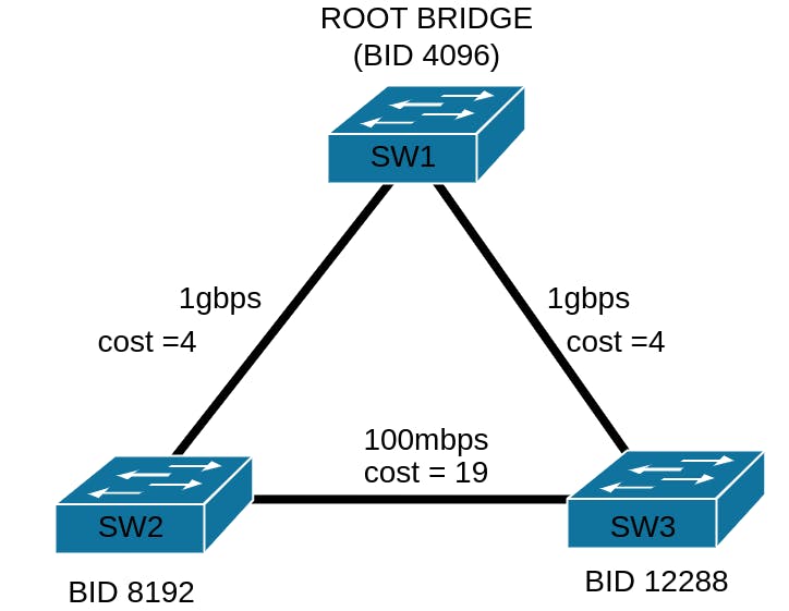
In the above diagram, you will see we have three switches. Notice I've given each switch their bridge IDs, the lowest being the root bridge. The bridge with BID 4096 is our root bridge.
Notice each link has its own cost. The two 1gbps uplinks from SW2 and SW3 have a cost of 4. The 100 Mbps link between SW2 and SW3 has a cost of 19.
Now let's think about the port roles in the above topology. What do you think the port roles will be? Take a look at the next diagram below.
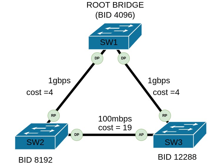
In the above diagram, I've inserted the port roles.
The link between SW1 to SW2 has a cost of 4. Therefore, the port on SW2 connected to SW1 will be assigned a root port. The link between SW3 to SW1 also has a cost of 4. Therefore, the port on SW3 connected to SW1 will also be assigned a root port. The link between SW2 and SW3 has a cost of 19 and therefore the port on SW2 connected to SW3 will be assigned a designated port role; the port on SW3 connected to SW2 will get the alternate port role since there needs to be a backup root port in RPVST+. Where's our backup port role in the topology? Well, because there are not enough designated ports to justify the use of a backup port in the topology, one won't be allocated.
Port States
Now that we've talked about the path costs and port roles, let's talk about the port states. In RPVST+, there are four port states:
Blocking: this port state takes place when traffic is being blocked as the port has received BPDUs where the bridge ID field does not match the root's bridge ID.
Learning: this port state takes place when the switch is getting ready to participate in forwarding traffic.
Forwarding: this is the port state where the port is actively forwarding traffic; this state can only take effect if it is not receiving BPDUs from a non-root bridge. Note: Depending on the position in the topology, ports in the forwarding state are still going to receive BPDUs from the root bridge. However, if the port role is designated port, it won't receive BPDUs but will continue to forward traffic.
Disabled: this port state takes place when the port does not participate in the RPVST+ topology. This port state is assigned to ports where PortFast is configured. PortFast will be discussed in the second article.
The Spanning-Tree Convergence Process
Now that I've explained BPDUs, bridge IDs, cost, port roles, and port states, let's discuss how the spanning-tree protocol converges across the topology.
The initial process
The convergence process is straightforward. Once you've connected all switches in the topology, all ports will go into the learning state.
Each switch will broadcast BPDUs out of the ports in the learning state. Each port will also receive BPDUs. In addition, all switches will see themselves as "root" initially. An election process will occur to tie-break who becomes the root bridge. Again, the lowest bridge ID in the topology will become the root bridge.
What if the bridge ID is left as the default value?
If you leave the bridge ID is left as the default of 32768, then the switch with the lowest MAC address will become the root bridge. It is HIGHLY RECOMMENDED that you do not leave the bridge ID as a default across all switches. A properly designed network will have a spanning-tree protocol implemented and tuned. A poorly designed network will have a spanning-tree protocol either left at defaults or misconfigured. While the lowest mac address serves as a mechanism for tie-breaking root bridge election, if the wrong root bridge is elected in the network topology (i.e. an access switch gets elected as the root bridge instead of a core switch), then traffic is not going to efficiently get up to the network core and this will result in higher latency and jitter.
After the Root Bridge election
Once the root bridge election is completed, the port roles and states change. Any ports that are point-to-point links to root bridges will transition from learning to forwarding, and their port roles will become "root ports".
Any ports that are not point-to-point with a root bridge will either transition to forwarding with a designated port role, or to blocking with an alternate port role. It depends on where they are in the topology.
Spanning-Tree Convergence Demo
I'm going to show you a demonstration of how the spanning-tree protocol will converge across this simple network topology, shown below.
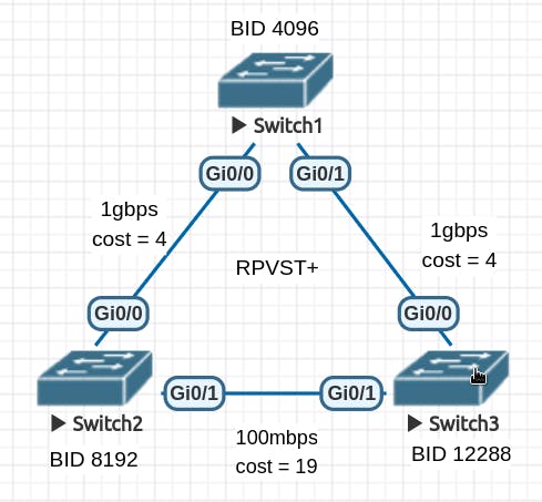
Imagine I just powered on these switches. They were already stage-configured with their startup-configs already written. RPVST+ was configured on these switches.
To show you the current port roles, I'm going to run a show spanning-tree command on all three switches.
Here's the output from switch 1. Notice each port is currently in the learning state. See the "STS" field.
*Nov 13 00:51:20.466: %SSH-5-ENABLED: SSH 1.99 has been enableds
s1#show spanning-tree

VLAN0001
  Spanning tree enabled protocol rstp
  Root ID    Priority    4097
             Address     5000.0001.0000
             This bridge is the root
             Hello Time   2 sec  Max Age 20 sec  Forward Delay 15 sec

  Bridge ID  Priority    4097   (priority 4096 sys-id-ext 1)
             Address     5000.0001.0000
             Hello Time   2 sec  Max Age 20 sec  Forward Delay 15 sec
             Aging Time  300 sec

Interface           Role Sts Cost      Prio.Nbr Type
------------------- ---- --- --------- -------- --------------------------------
Gi0/0               Desg LRN 4         128.1    P2p
Gi0/1               Desg LRN 4         128.2    P2p
Gi0/2               Desg LRN 4         128.3    P2p
Gi0/3               Desg LRN 4         128.4    P2p
Gi1/0               Desg LRN 4         128.5    P2p
Gi1/1               Desg LRN 4         128.6    P2p
Gi1/2               Desg LRN 4         128.7    P2p
Gi1/3               Desg LRN 4         128.8    P2p
Below is the output from switch 2. Again, each port is in the learning state. Also, notice how the switch thinks it is the root bridge, even though it has a BID of 8192.
s2>en
s2#show spanning-tree

VLAN0001
  Spanning tree enabled protocol rstp
  Root ID    Priority    8193
             Address     5000.0002.0000
             This bridge is the root
             Hello Time   2 sec  Max Age 20 sec  Forward Delay 15 sec

  Bridge ID  Priority    8193   (priority 8192 sys-id-ext 1)
             Address     5000.0002.0000
             Hello Time   2 sec  Max Age 20 sec  Forward Delay 15 sec
             Aging Time  300 sec

Interface           Role Sts Cost      Prio.Nbr Type
------------------- ---- --- --------- -------- --------------------------------
Gi0/0               Desg LRN 4         128.1    P2p
Gi0/1               Desg LRN 19        128.2    P2p
Gi0/2               Desg LRN 4         128.3    P2p
Gi0/3               Desg LRN 4         128.4    P2p
Gi1/0               Desg LRN 4         128.5    P2p
Gi1/1               Desg LRN 4         128.6    P2p
Gi1/2               Desg LRN 4         128.7    P2p
Gi1/3               Desg LRN 4         128.8    P2p
Here's the output for switch 3. Again, we have each port in a learning state, and this switch thinks the root bridge is itself.
s3>en
s3#show spanning-tree

VLAN0001
  Spanning tree enabled protocol rstp
  Root ID    Priority    12289
             Address     5000.0003.0000
             This bridge is the root
             Hello Time   2 sec  Max Age 20 sec  Forward Delay 15 sec

  Bridge ID  Priority    12289  (priority 12288 sys-id-ext 1)
             Address     5000.0003.0000
             Hello Time   2 sec  Max Age 20 sec  Forward Delay 15 sec
             Aging Time  300 sec

Interface           Role Sts Cost      Prio.Nbr Type
------------------- ---- --- --------- -------- --------------------------------
Gi0/0               Desg LRN 4         128.1    P2p
Gi0/1               Desg LRN 19        128.2    P2p
Gi0/2               Desg LRN 4         128.3    P2p
Gi0/3               Desg LRN 4         128.4    P2p
Gi1/0               Desg LRN 4         128.5    P2p
Gi1/1               Desg LRN 4         128.6    P2p
Gi1/2               Desg LRN 4         128.7    P2p
Gi1/3               Desg LRN 4         128.8    P2p
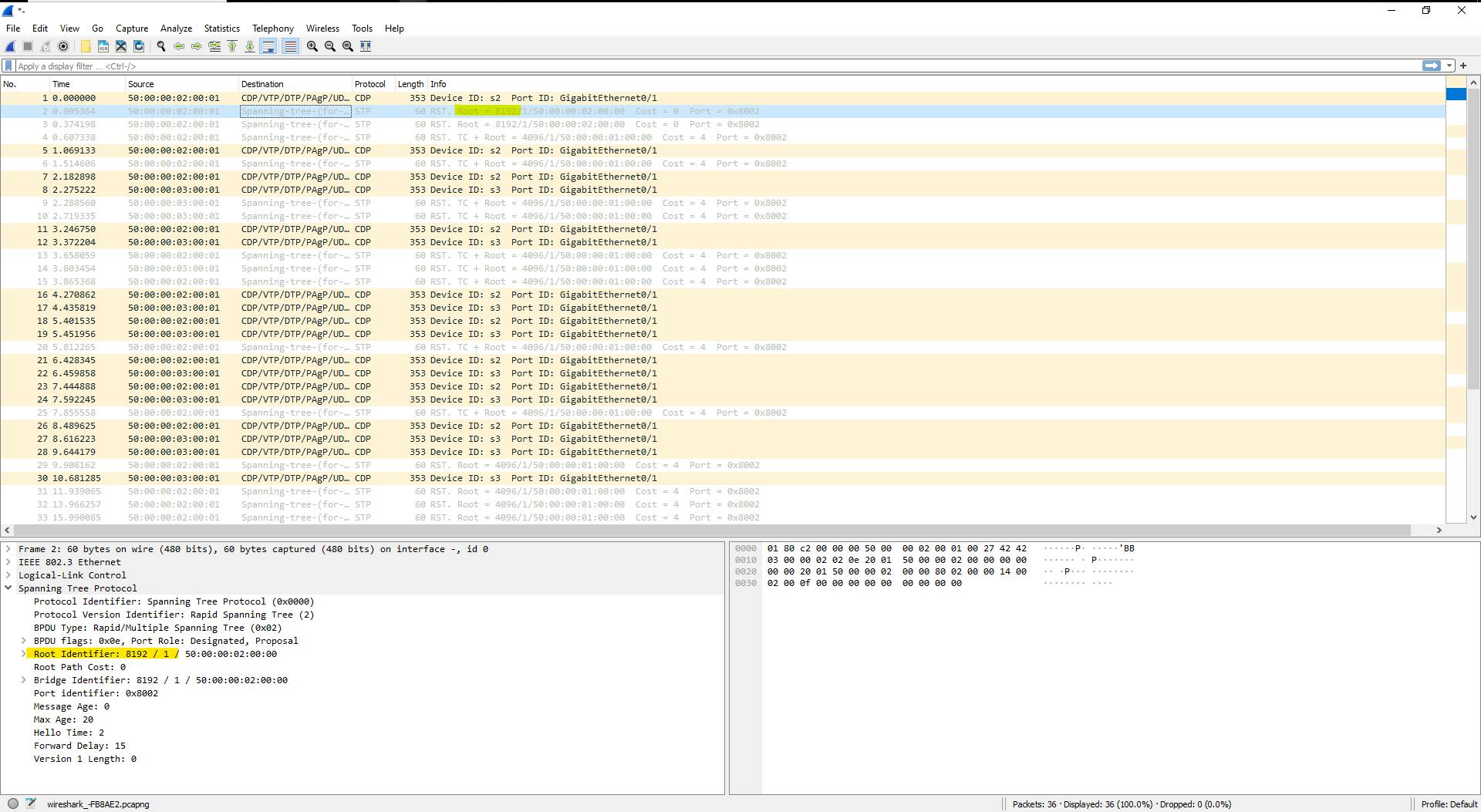
Below are a few screenshots from Wireshark depicting BPDU captures. Notice how in the beginning, the root bridge ID in the first BPDU is 8192 (switch 2). The election process is taking place.
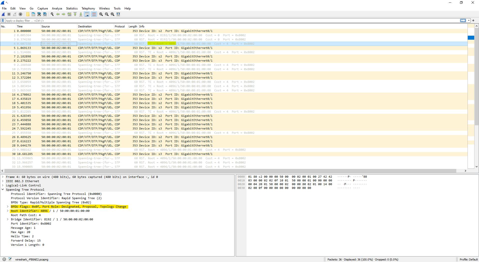
In the second screenshot, you'll see that the root bridge identifier changed to 4096. Also, notice that a "topology change" notice was added to the BPDU flags field. The "topology change" notice lets switches know that there is an update to the topology and that they need to adjust their port states.
In the third screenshot, you'll see a BPDU sent from switch 2 (bridge ID 8192), to switch 3. The root identifier in the BPDU is 4096. So, switch 3 is receiving BPDUs from a non-root bridge.
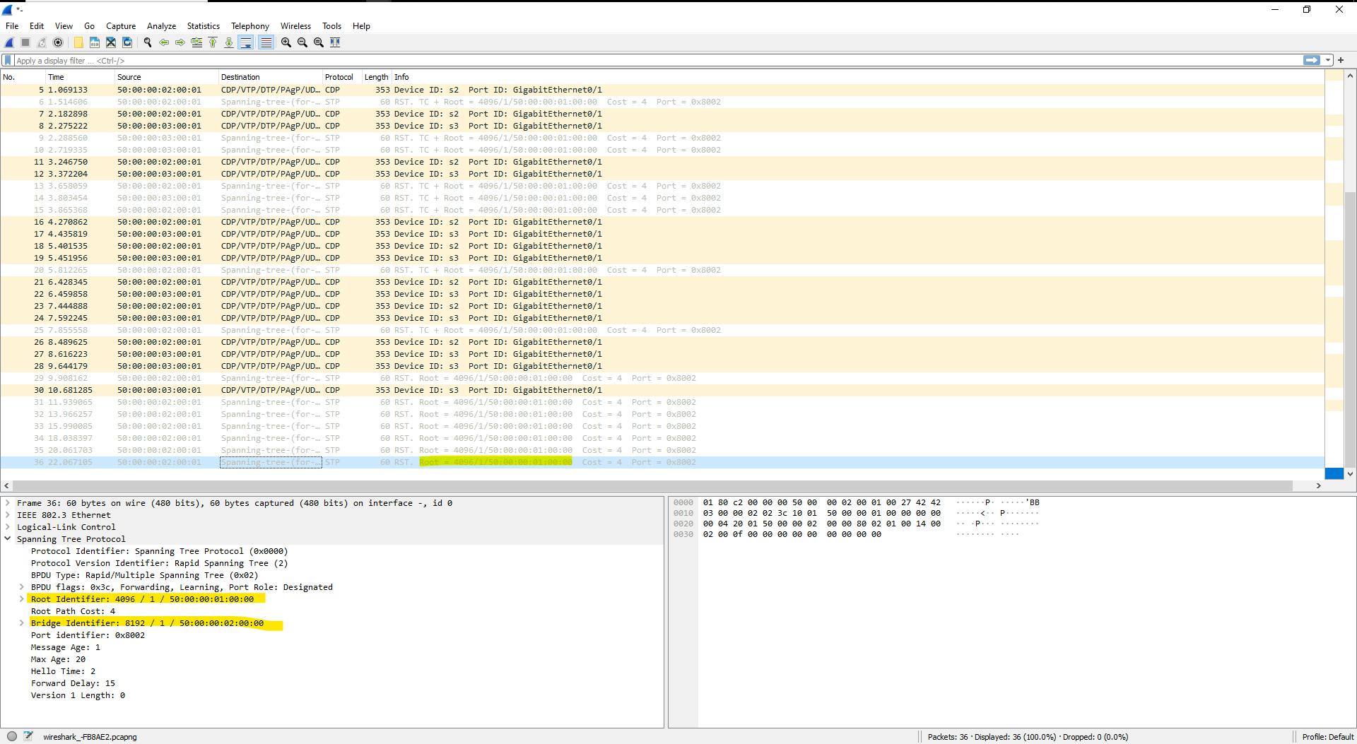
At this point, the port on switch 3 connected to switch 2 should be in blocking status, and its port role should be alternate port because if the link between switch 3 to switch 1 fails, it can take advantage of the link to switch 2 as an alternative path back to switch 1. Let's check and see if g0/1 on switch 3 is an alternate port and in blocking status.
Running the show spanning-tree interface command will allow us to see the spanning tree status of each port.
Here's what we get for switch 3 interface g0/1:
s3>enable
s3#show spanning-tree interface g0/1

Vlan                Role Sts Cost      Prio.Nbr Type
------------------- ---- --- --------- -------- --------------------------------
VLAN0001            Altn BLK 19        128.2    P2p
s3#
As you can see above, interface g0/1 on switch 3, which connects to switch 2, is currently in a blocked state. The reason for this is that it's receiving BPDUs from a neighboring switch that is not the root bridge, which was proven in the third Wireshark screenshot.
Let's check out the statuses of other ports on switch 3.
Running the show spanning-tree command will give us an output of all currently up interfaces and their spanning tree statuses.
*Nov 13 01:23:00.405: %LINEPROTO-5-UPDOWN: Line protocol on Interface GigabitEthernet1/3, changed state to down
s3#show spanning-tree

VLAN0001
  Spanning tree enabled protocol rstp
  Root ID    Priority    4097
             Address     5000.0001.0000
             Cost        4
             Port        1 (GigabitEthernet0/0)
             Hello Time   2 sec  Max Age 20 sec  Forward Delay 15 sec

  Bridge ID  Priority    12289  (priority 12288 sys-id-ext 1)
             Address     5000.0003.0000
             Hello Time   2 sec  Max Age 20 sec  Forward Delay 15 sec
             Aging Time  300 sec

Interface           Role Sts Cost      Prio.Nbr Type
------------------- ---- --- --------- -------- --------------------------------
Gi0/0               Root FWD 4         128.1    P2p
Gi0/1               Altn BLK 19        128.2    P2p
As you can see above, g0/0 is a root port and in forwarding status, since it is receiving BPDUs directly from the root bridge.
Let's check the port roles on switch 2. I'll run the show spanning-tree command again.
s2#show spanning-tree

VLAN0001
  Spanning tree enabled protocol rstp
  Root ID    Priority    4097
             Address     5000.0001.0000
             Cost        4
             Port        1 (GigabitEthernet0/0)
             Hello Time   2 sec  Max Age 20 sec  Forward Delay 15 sec

  Bridge ID  Priority    8193   (priority 8192 sys-id-ext 1)
             Address     5000.0002.0000
             Hello Time   2 sec  Max Age 20 sec  Forward Delay 15 sec
             Aging Time  300 sec

Interface           Role Sts Cost      Prio.Nbr Type
------------------- ---- --- --------- -------- --------------------------------
Gi0/0               Root FWD 4         128.1    P2p
Gi0/1               Desg FWD 19        128.2    P2p
Above g0/0 is a root port and forwarding. g0/1 is a designated port and forwarding.
g0/0 is a root port because it is connected to the root bridge and receives BPDUs directly from the root bridge.
g0/1 is in a designated state because it's not connected to the root bridge. Because it has a bridge ID of 8192 and switch 3 has a bridge ID of 12288, this side of the point-to-point link got the designated port and forwarding status. However, traffic will not go across this link because it will get blocked on the other end.
Let's check the status of switch 1.
*Nov 13 01:29:20.903: %LINEPROTO-5-UPDOWN: Line protocol on Interface GigabitEth                                                                              ernet1/3, changed state to down
s1#show spanning-tree

VLAN0001
  Spanning tree enabled protocol rstp
  Root ID    Priority    4097
             Address     5000.0001.0000
             This bridge is the root
             Hello Time   2 sec  Max Age 20 sec  Forward Delay 15 sec

  Bridge ID  Priority    4097   (priority 4096 sys-id-ext 1)
             Address     5000.0001.0000
             Hello Time   2 sec  Max Age 20 sec  Forward Delay 15 sec
             Aging Time  300 sec

Interface           Role Sts Cost      Prio.Nbr Type
------------------- ---- --- --------- -------- --------------------------------
Gi0/0               Desg FWD 4         128.1    P2p
Gi0/1               Desg FWD 4         128.2    P2p


s1#
Notice in the above output, that both ports are designated ports, and in the forwarding status. The reason why both ports are in designated status is because they're connected to downstream switches that are not the root bridge. The root bridge will have designated ports for every port that is in up/up status unless the port was configured for PortFast.
This covers the operations of the spanning-tree protocol.
Conclusion
In this article, I discussed the spanning-tree protocol, and how it operates in Cisco Catalyst switches. I discussed RPVST+, and the details of BPDUs, port roles, port states, and the convergence process of the spanning-tree protocol.
In the next article, I'm going to discuss how to configure RPVST+ on Cisco Catalyst switches.
Thanks for reading this article. I hope you found this article helpful and entertaining. Feel free to leave feedback in the comments. Stick around for part 2 of the spanning-tree protocol series.
