


In this article, I will demonstrate how to set up basic configurations of RPVST+ on Cisco Catalyst switches. This article expands on my previous article covering how RPVST+ operates on Cisco Catalyst switches.
Introduction
When configuring RPVST+ on Cisco Catalyst switches, you should first configure:
RPVST+ mode
Priority (per VLAN)
Optional parameters:
Adjust Hello Time
Adjust Max Age
Adjust Forward Delay
Once you've configured the basic settings, you should then focus on tuning. The process of tuning RPVST+ consists of the following:
Enabling portfast and bpdu guard on access ports
Adjusting port costs
Configuring bridge assurance
Configuring root guard
Let's begin with the basic configuration.
Activate RPVST+ Mode
When you first unbox your Cisco Catalyst switch, it may or may not be running RPVST+. To ensure it is, you should change the spanning-tree mode to rapid-pvst. Use the spanning-tree mode rapid-pvst command to do so:
sw1#config t
Enter configuration commands, one per line.  End with CNTL/Z.
sw1(config)#spanning-tree mode rapid-pvst
sw1(config)#end
Use the show spanning-tree command to validate the version of spanning-tree running. Note that it says "Spanning tree enabled protocol rstp".
sw1#show spanning-tree
*Nov 19 14:09:49.707: %SYS-5-CONFIG_I: Configured from console by console

VLAN0001
  ** Spanning tree enabled protocol rstp
  Root ID    Priority    32769
             Address     5000.0001.0000
             This bridge is the root
             Hello Time   2 sec  Max Age 20 sec  Forward Delay 15 sec

  Bridge ID  Priority    32769  (priority 32768 sys-id-ext 1)
             Address     5000.0001.0000
             Hello Time   2 sec  Max Age 20 sec  Forward Delay 15 sec
             Aging Time  300 sec

Interface           Role Sts Cost      Prio.Nbr Type
------------------- ---- --- --------- -------- --------------------------------
Po1                 Desg BLK 3         128.65   P2p
Po2                 Desg BLK 3         128.66   P2p
Po3                 Desg BLK 3         128.67   P2p
Po4                 Desg BLK 3         128.68   P2p
Configure Bridge Priority
Next, you need to assign bridge priorities to each switch that will operate in your enterprise network. The core switch should always be given the lowest bridge priority. Lower priority = higher precedence. The switch with the highest precedence will become the root bridge.
In an enterprise campus network, start from your core and work your way down. Give your first core switch priority 4096, and give your second core switch priority 8192. Then, assign bridge priorities across your distribution switches. Why should your core switches be root bridges? Because core switches are the fastest switches in your network. You will want enterprise network traffic to go from source to destination as quickly as possible, and that is done by passing the packet along from the access layer, to the core layer. Remember, the root bridge is the top-level switch in the topology. You want all traffic going towards your root bridge.
There is generally no need to assign bridge IDs to your access layer switches. You typically do not daisy chain access switches together, and because these switches sit at the bottom of the spanning tree - there is no reason to adjust priorities to those switches. You should never daisy chain access switches. I will be writing a future article explaining why that is and I'll replace this note with a hyperlink when it's published.
Below demonstrates configuring bridge priority on each switch in accordance with the bridge priorities defined in the network diagram.
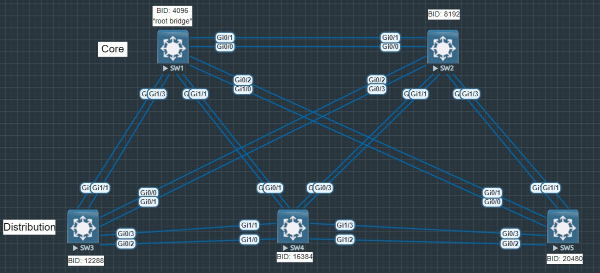
Use the spanning-tree vlan [id] priority [bid] command to set the bridge priority. If you have multiple VLANs on your switch, you can use a VLAN range. The below example shows me configuring SW1 for bridge priority 4096 across VLANs 1-4.
sw1#config t
Enter configuration commands, one per line.  End with CNTL/Z.
sw1(config)#spanning-tree vlan 1-4 priority 4096
sw1(config)#end
Now I will repeat this process for the remaining switches in the topology.
sw2#config t
Enter configuration commands, one per line.  End with CNTL/Z.
sw2(config)#spanning-tree vlan 1-4 priority 8192
sw2(config)#end
sw3#config t
Enter configuration commands, one per line.  End with CNTL/Z.
sw3(config)#spanning-tree vlan 1-4 priority 12288
sw3(config)#end
sw4#config t
Enter configuration commands, one per line.  End with CNTL/Z.
sw4(config)#spanning-tree vlan 1-4 priority 16384
sw4(config)#end
sw5#config t
Enter configuration commands, one per line.  End with CNTL/Z.
sw5(config)#spanning-tree vlan 1-4 priority 20480
sw5(config)#end
Now that the switch bridge priorities have been configured, we can use the show spanning-tree command to validate the bridge priority of each switch. For timekeeping, I will show you the output from SW1 and SW5.
*Nov 19 16:16:16.202: %SYS-5-CONFIG_I: Configured from consol
sw1#show spanning-tree

VLAN0001
  Spanning tree enabled protocol rstp
  Root ID    Priority    4097
             Address     5000.0001.0000
             This bridge is the root
             Hello Time   2 sec  Max Age 20 sec  Forward Delay 15 sec

  Bridge ID  Priority    4097   (priority 4096 sys-id-ext 1)
             Address     5000.0001.0000
             Hello Time   2 sec  Max Age 20 sec  Forward Delay 15 sec
             Aging Time  300 sec

Interface           Role Sts Cost      Prio.Nbr Type
------------------- ---- --- --------- -------- --------------------------------
Po1                 Desg FWD 3         128.65   P2p
Po2                 Desg FWD 3         128.66   P2p
Po3                 Desg FWD 3         128.67   P2p
Po4                 Desg FWD 3         128.68   P2p
Notice in the above output that SW1 is the root bridge now because the bridge priority has been set to the lowest value among all the switches in the spanning-tree.
Let's look at SW5.
sw5#show spanning-tree

VLAN0001
  Spanning tree enabled protocol rstp
  Root ID    Priority    4097
             Address     5000.0001.0000
             Cost        3
             Port        66 (Port-channel2)
             Hello Time   2 sec  Max Age 20 sec  Forward Delay 15 sec

  Bridge ID  Priority    20481  (priority 20480 sys-id-ext 1)
             Address     5000.0005.0000
             Hello Time   2 sec  Max Age 20 sec  Forward Delay 15 sec
             Aging Time  300 sec

Interface           Role Sts Cost      Prio.Nbr Type
------------------- ---- --- --------- -------- --------------------------------
Po1                 Altn BLK 3         128.65   P2p
Po2                 Root FWD 3         128.66   P2p
Po3                 Altn BLK 3         128.67   P2p
Notice how in the show output for SW5 it reports bridge ID 4097 as the root (4097 - the extended system ID of 1 = 4096).
At this point, bridge priorities are configured. Let's move on.
Optional Basic Parameters
There are three other parameters that can be configured. They are:
Hello Time
Max Age
Forward Delay
I am not going to adjust the timers in my topology, but if you were to configure them yourself, below would be how you'd adjust them...
Hello Time
Use the spanning-tree vlan [id] hello-time [1-10] command, for example:
sw#config t
sw5(config)#spanning-tree vlan 1 hello-time 5
To verify, use the show spanning-tree bridge detail command, and look for the "Hello Time" value:
sw5#show spanning-tree bridge detail
VLAN0001
  Bridge ID  Priority    20481  (priority 20480 sys-id-ext 1)
             Address     5000.0005.0000
             Hello Time   5 sec  Max Age  Forward Delay
Max Age
Use the spanning-tree vlan [id] max-age [6-40] command, for example:
sw5(config)#spanning-tree vlan 1 max-age 15
sw5(config)#end
*Nov 19 16:26:07.153: %SYS-5-CONFIG_I: Configured from conso
sw5#show spanning-tree bridge detail
VLAN0001
  Bridge ID  Priority    20481  (priority 20480 sys-id-ext 1)
             Address     5000.0005.0000
             Hello Time   5 sec  Max Age 15 sec  Forward Delay
sw5#
Again, to verify, use the show spanning-tree bridge detail command, and look for the "Max Age" value.
Forward Delay
Use the spanning-tree vlan [id] forward-time [4-30] command to adjust the forward delay. Use the show spanning-tree bridge detail command again to validate the configuration:
sw5(config)#spanning-tree vlan 1 forward-time 20
sw5(config)#end
*Nov 19 16:28:41.578: %SYS-5-CONFIG_I: Configured from console
sw5#show spanning-tree bridge detail
VLAN0001
  Bridge ID  Priority    20481  (priority 20480 sys-id-ext 1)
             Address     5000.0005.0000
             Hello Time   5 sec  Max Age 15 sec  Forward Delay 20 sec
Tuning
Now that basic settings are configured, we can start tuning the RPVST+ spanning tree.
PortFast
The first item to configure when tuning spanning-tree is PortFast. What is PortFast? It is a mechanism applied to access ports that allows the ports to bypass spanning-tree for immediate convergence.
Now, in RPVST+, the convergence time is usually less than 10 seconds. That's an improvement from the old PVST+ and older IEEE STP standards. In the old days, it took up to 50 seconds or more for convergence. In other words, when you plug a computer into a Catalyst switch, the port won't start forwarding traffic until after 8 to 50 seconds. Enabling PortFast on the port disables spanning-tree on it, thus allowing you to skip the wait for convergence on the port.
Be very careful when using PortFast. Always enable BPDU guard in conjunction with PortFast. Otherwise, you run the risk of creating a network loop if an end user sneaks a switch in and plugs it into a wall outlet in your office.
To configure portfast, use the spanning-tree portfast edge command on each access port in your topology:
access_sw1(config)#int g0/1
access_sw1(config-if)#spanning-tree portfast edge
%Warning: portfast should only be enabled on ports connected to a single
 host. Connecting hubs, concentrators, switches, bridges, etc... to this
 interface  when portfast is enabled, can cause temporary bridging loops.
 Use with CAUTION

%Portfast has been configured on GigabitEthernet0/1 but will only
 have effect when the interface is in a non-trunking mode.
access_sw1(config-if)#end
access_sw1#
*Nov 19 16:48:15.975: %SYS-5-CONFIG_I: Configured from console by console
To verify, use show run interface [id] command, followed by show spanning-tree vlan 1.
access_sw1#show run interface g0/1
Building configuration...

Current configuration : 83 bytes
!
interface GigabitEthernet0/1
 negotiation auto
 spanning-tree portfast edge
end

access_sw1#show spanning-tree vlan 1

VLAN0001
  Spanning tree enabled protocol rstp
  Root ID    Priority    4097
             Address     5000.0001.0000
             Cost        7
             Port        1 (GigabitEthernet0/0)
             Hello Time   2 sec  Max Age 20 sec  Forward Delay 15 sec

  Bridge ID  Priority    32769  (priority 32768 sys-id-ext 1)
             Address     5000.0006.0000
             Hello Time   2 sec  Max Age 20 sec  Forward Delay 15 sec
             Aging Time  300 sec

Interface           Role Sts Cost      Prio.Nbr Type
------------------- ---- --- --------- -------- --------------------------------
Gi0/0               Root FWD 4         128.1    P2p
Gi0/1               Desg FWD 4         128.2    P2p Edge
Gi0/2               Desg FWD 4         128.3    P2p
Gi0/3               Desg FWD 4         128.4    P2p
Gi1/0               Desg FWD 4         128.5    P2p
Gi1/1               Desg FWD 4         128.6    P2p
Gi1/2               Desg FWD 4         128.7    P2p
Gi1/3               Desg FWD 4         128.8    P2p
Notice in the output for the show run command, you can see that portfast is configured for the desired port. In the show spanning-tree vlan 1 command, you can seee that g0/1 is a designated port, is forwarding, and the link type is "p2p edge".
BPDU guard
BPDU guard should be used in conjunction with PortFast. Once you've enabled PortFast, you should enable BPDU guard. BPDU guard is a security and quality assurance feature. BPDU guard prevents switches from joining the topology and causing a temporary loop, and in addition, to that it mitigates unauthorized switches from getting plugged into the topology.
To enable bpdu guard, use the spanning-tree bpduguard enable command on the access port:
access_sw1#conf t
Enter configuration commands, one per line.  End with CNTL/Z.
access_sw1(config)#int g0/1
access_sw1(config-if)#spanning-tree bpduguard enable
To verify, run the show run interface [id] command:
access_sw1#
*Nov 19 16:53:50.245: %SYS-5-CONFIG_I: Configured from console by console
access_sw1#show run interface g0/1
Building configuration...

Current configuration : 115 bytes
!
interface GigabitEthernet0/1
 negotiation auto
 spanning-tree portfast edge
 spanning-tree bpduguard enable
end
In the above output, you can see that bpduguard is enabled on the port.
It should be noted that when you use bpduguard, the port goes into an ERR-DISABLED state. Let me demonstrate this...
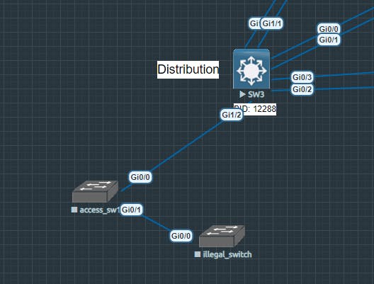
I've just plugged in an illegal switch into port g0/1 on access_sw1. Let me show you what happens in Cisco IOS when the switch processor recognizes BPDUs on g0/1...
access_sw1#show log
*Nov 19 16:58:43.526: %SPANTREE-2-BLOCK_BPDUGUARD: Received BPDU on port Gi0/1 with BPDU Guard enabled. Disabling port.
*Nov 19 16:58:43.526: %PM-4-ERR_DISABLE: bpduguard error detected on Gi0/1, putting Gi0/1 in err-disable state
In the above, you can see from the log buffer, a BPDU was received on g0/1, and the switch put port g0/1 into a blocking state. Let's do a show spanning-tree vlan 1 command to see the state of the port.
access_sw1#show spanning-tree vlan 1

VLAN0001
  Spanning tree enabled protocol rstp
  Root ID    Priority    4097
             Address     5000.0001.0000
             Cost        7
             Port        1 (GigabitEthernet0/0)
             Hello Time   2 sec  Max Age 20 sec  Forward Delay 15 sec

  Bridge ID  Priority    32769  (priority 32768 sys-id-ext 1)
             Address     5000.0006.0000
             Hello Time   2 sec  Max Age 20 sec  Forward Delay 15 sec
             Aging Time  300 sec

Interface           Role Sts Cost      Prio.Nbr Type
------------------- ---- --- --------- -------- --------------------------------
Gi0/0               Root FWD 4         128.1    P2p
Gi0/2               Desg FWD 4         128.3    P2p
Gi0/3               Desg FWD 4         128.4    P2p
Gi1/0               Desg FWD 4         128.5    P2p
Gi1/1               Desg FWD 4         128.6    P2p
Gi1/2               Desg FWD 4         128.7    P2p
Gi1/3               Desg FWD 4         128.8    P2p
Where's g0/1? It's not showing in the output. Why? Because it is in an error disabled state. If I run show interface g0/1, you can see the err-disabled state.
access_sw1#show interface g0/1
GigabitEthernet0/1 is down, line protocol is down (err-disabled)
  Hardware is iGbE, address is 5000.0006.0001 (bia 5000.0006.0001)
How do you bring g0/1 back up? You have to restart the switch port by running shut and no shut against it.
access_sw1#conf t
Enter configuration commands, one per line.  End with CNTL/Z.
access_sw1(config)#int g0/1
access_sw1(config-if)#shut
access_sw1(config-if)#no shut
access_sw1(config-if)#end
access_sw1#sh
*Nov 19 17:05:03.246: %SYS-5-CONFIG_I: Configured from console by conso
access_sw1#show ip int b
Interface              IP-Address      OK? Method Status                Protocol
GigabitEthernet0/0     unassigned      YES unset  up                    up
GigabitEthernet0/1     unassigned      YES unset  up                    up
GigabitEthernet0/2     unassigned      YES unset  up                    up
GigabitEthernet0/3     unassigned      YES unset  up                    up
GigabitEthernet1/0     unassigned      YES unset  up                    up
GigabitEthernet1/1     unassigned      YES unset  up                    up
GigabitEthernet1/2     unassigned      YES unset  up                    up
GigabitEthernet1/3     unassigned      YES unset  up                    up
The port is now back up after doing so, but if the switch were still plugged in, then the port would immediately go back into the err-disabled state as soon as it received a BPDU from the other switch.
To wrap up this section: always enable BPDU guard in conjunction to PortFast. It will save you if you use it, and it will destroy you if you don't use it.
Adjusting port costs
As previously mentioned in the last article, port costs can be adjusted. Cost is a factor that's determined in assigning port roles (i.e. designated, root, or alternate port) to each switch port. Port costs are relative to link speed (i.e. 10/100/1000 mbps).
You can optionally adjust the port cost for each interface in your spanning-tree topology. I am not going to do so because it's a feature that you don't necessarily need to modify.
Below are the commands to configure and verify port costs for a Cisco Catalyst switch:
sw4#conf t
Enter configuration commands, one per line.  End with CNTL/Z.
sw4(config)#int po1
sw4(config-if)#spanning-tree cost 2
sw4(config-if)#end
sw4#show spanning
*Nov 19 17:17:04.413: %SYS-5-CONFIG_I: Configured from conso
sw4#show spanning-tree

VLAN0001
  Spanning tree enabled protocol rstp
  Root ID    Priority    4097
             Address     5000.0001.0000
             Cost        2
             Port        65 (Port-channel1)
             Hello Time   2 sec  Max Age 20 sec  Forward Delay 15 sec

  Bridge ID  Priority    16385  (priority 16384 sys-id-ext 1)
             Address     5000.0004.0000
             Hello Time   2 sec  Max Age 20 sec  Forward Delay 15 sec
             Aging Time  300 sec

Interface           Role Sts Cost      Prio.Nbr Type
------------------- ---- --- --------- -------- --------------------------------
Po1                 Root FWD 2         128.65   P2p
Bridge assurance & root guard
Bridge assurance is an important piece to the spanning-tree topology. Especially nowadays. RPVST+ has a feature known as bridge assurance, and the idea is to keep a blocked port in the blocking state even if it doesn't receive a BPDU.
In the event a switch in the spanning-tree fails, whether it be due to a processor failure that renders it to act as a hub, or a complete failure of the device, the port connected to that device will not transition out of the blocking state in order to prevent loops.
Root guard is a feature that prevents switches in the topology from trusting an unauthorized switch configured with more preceding settings than your original root bridge. You should enable root guard on non-root-ports for it to be effective. Root guard prevents a non-root-port from changing to a root port if for whatever reason it receives more interesting BPDUs from a different switch configured to act as a root bridge.
Bridge assurance is usually enabled by default and therefore you should not have to do anything specific for it to work. However, to ensure that it is enabled, you can run the spanning-tree bridge-assurance command in global configuration mode:
sw4(config)#spanning-tree bridge assurance
To verify, run the show spanning-tree summary command which will output the status of bridge assurance:
sw4(config)#end
*Nov 19 17:30:29.926: %SYS-5-CONFIG_I: Configured from consol
sw4#show spanning-tree summary
Switch is in rapid-pvst mode
Root bridge for: none
Extended system ID                      is enabled
Portfast Default                        is disabled
Portfast Edge BPDU Guard Default        is disabled
Portfast Edge BPDU Filter Default       is disabled
Loopguard Default                       is disabled
PVST Simulation Default                 is enabled but inactive in rapid-pvst mode
Bridge Assurance                        is enabled
To configure root guard, select non root ports in your topology to enable it. Once you've determined them, run the spanning-tree guard root command on the interface.
sw4#show spanning-tree

VLAN0001
  Spanning tree enabled protocol rstp
  Root ID    Priority    4097
             Address     5000.0001.0000
             Cost        2
             Port        65 (Port-channel1)
             Hello Time   2 sec  Max Age 20 sec  Forward Delay 15 sec

  Bridge ID  Priority    16385  (priority 16384 sys-id-ext 1)
             Address     5000.0004.0000
             Hello Time   2 sec  Max Age 20 sec  Forward Delay 15 sec
             Aging Time  300 sec

Interface           Role Sts Cost      Prio.Nbr Type
------------------- ---- --- --------- -------- --------------------------------
Gi1/0               Desg FWD 4         128.5    P2p
Gi1/1               Desg FWD 4         128.6    P2p
Po1                 Root FWD 2         128.65   P2p
Po2                 Desg FWD 3         128.66   P2p
Po3                 Desg FWD 3         128.67   P2p


sw4#conf t
Enter configuration commands, one per line.  End with CNTL/Z.
sw4(config)#int g1/0
sw4(config-if)#spanning-tree guard root
sw4(config-if)#int
*Nov 19 17:34:29.959: %SPANTREE-2-ROOTGUARD_CONFIG_CHANGE: Root guard enabled on port GigabitEthernet1
sw4(config-if)#int g1/1
sw4(config-if)#spanning-tree guard root
sw4(config-if)#
*Nov 19 17:34:38.305: %SPANTREE-2-ROOTGUARD_CONFIG_CHANGE: Root guard enabled on port GigabitEthernet1/1.
sw4(config-if)#end
sw4#show
*Nov 19 17:34:41.915: %SYS-5-CONFIG_I: Configured from console by co
sw4#show run interface g1/0
Building configuration...

Current configuration : 80 bytes
!
interface GigabitEthernet1/0
 negotiation auto
 spanning-tree guard root
end

sw4#show run interface g1/1
Building configuration...

Current configuration : 80 bytes
!
interface GigabitEthernet1/1
 negotiation auto
 spanning-tree guard root
end
Conclusion
This article covered configuring RPVST+. This article demonstrated configuring basic settings, which included:
Activating RPVST+
Configuring bridge IDs
Configuring hello time, max age, and forward delay.
This article also demonstrated tuning RPVST+, which included:
Configuring portfast and bpdu guard
Adjusting port costs
Enabling bridge assurance
Configuring root guard
The purpose of this article was to provide you with basic demonstrations for configuring RPVST+. It is not designed to provide the reader with best practice scenarios for RPVST+ and should not be taken in that extent. Any criticism of this article is welcome but please be mindful that this is not supposed to be a comprehensive case study on best practices.
This article is designed to help those preparing for the CCNA or CCNP ENCOR learn and understand Cisco RPVST+.
Thanks for reading this article. I hope you found this article helpful and entertaining. Feel free to leave feedback in the comments. Stick around for part 2 of the spanning-tree protocol series.